Optical Networking: Basics, DWDM, ROADM
by Eric Stewart on Oct.26, 2015, under Internet Service Providers, Networking, Technology
Yes, I can be annoyingly nebulous when I describe my current $JOB situation. It’s going to be a bit more annoying because I need to refer to the geographical area in general terms.
I work for a University. We’re kind of big, with multiple campuses scattered around our area, which also involves a large body of water. We also have various satellite offices and a presence at a local hospital, as well as connectivity for three different service providers (one that essentially provides Internet 2 access, the other two being full regular Internet). For the most part, we use an ELAN (actually a Metro-Ethernet) provided by a local service provider for connectivity to several of these places, as well as providing some “last mile” connectivity between ourselves and a few of our WAN service providers. The connectivity, for the most part, is 1Gbps.
Those above me started doing the math and talked to a fiber provider (a la “dark fiber“). In time, they figured they could provide us a “ring” around the area that would hit all of the sites we’d need. It would essentially be two independent paths between any two sites for redundancy purposes. In the long run, we’d save money and be able to bump our site-to-site speed to 10 Gbps … with the ability (with sufficient financial outlay) to go 100 Gbps. If the fiber was physically broken, it’d be the provider’s problem. Otherwise, it was leased to us and we’d be responsible for the light on it.
This is not as simple as putting two switches on each end of a given strand at two different sites. It becomes what I’ve personally termed, “Layer 1.5”.
You use equipment (which I will go into a little detail about later) to designate a wave-length around the ring (one way or the other, or both for redundancy) as being the connection between two sites. Keep in mind, though, that this wavelength might just pass through other sites on it’s way between the designated sites, and that other wavelengths will be added or dropped from the light going through the fiber as needed for connections between two other sites.
That may sound simple, and at a high level, it is. It’s when you start getting into implementation that it gets a little more interesting.
Cisco has “Cisco Transport Planner” (CTP). I personally haven’t had two much interaction with this software yet; you essentially map your connections out, indicating distances between your sites, which sites need to connect back and forth, and what kinds of protection or redundancy you’d like, and it will spit out a list of equipment and some XML files to use for configuring that equipment (not including spares, so be ready to order a little extra).
But it’s still not that simple … this is just a step on the way to implementation.
Before going any further, there’s one or a few things to keep in mind:
- Speed, both in data rate, but also the moments involved in interpreting and transmitting data, are key. In other words, anything that slows things down is bad. Moments of interpretation at each point can add up.
- Because of this, if at all possible, you don’t want to spend time converting a light signal to an electrical signal if you’re just going to pump out a light signal again.
- When all is said and done, if you’re learning this stuff, trace the light – connect an individual Tx to an Rx and find out what happens when something is Rx’d, and where it next gets Tx’d. That might help you understand just a little more of what’s going on.
Here’s an idea of why it can get so confusing … even on a small scale:

Site 1 Wired; Site 2 no cards
What you see here is a two-site lab. The Site 2 Engineer hadn’t installed his cards and cabling yet. But as you can see from Site 1, there’s a lot of single strands of LC-LC fiber jumpers. Now, for the most part, any strand going from a given Tx-to-Rx strand has a partner going Rx-to-Tx on the corresponding ports. And CTP can provide you a per-strand layout of what cable gets plugged in where on either side. The thing is, while there is a backplane (you can see some of it in Site 2’s chassis), it’s not used as much as you’d think – again, keep in mind that you don’t translate between light and electrical if you don’t need to.
Each Site 1 has:
- Two shelves
- Two TNCE control cards
- Two ROADM cards
- Two OTU2-XP cards
With the cards contained in an NCS-2006 chassis. Each set of three cards are related, and the two sets “face opposite directions” – think, in a ring topology, that one set “faces” clockwise, the other set faces counter-clockwise (and a given set at one site then connects to a specific set at the other site). In this lab, two circuits (operating in a specified bandwidth of light) were set up to provide connectivity between two switches (one at each site) – one circuit being active, the other being in standby (using a Y-Cable protect method … which I won’t go into any more detail about).

Close up of part of a passive shelf
The shelves are each 40 channel shelves and have ports for each individual wavelength, and a combined port. A given shelf is paired up with one set of cards. At the right should be a close-up of the shelf (which is unpowered). What the shelf does is takes in (via the Rx ports on the left side of the shelf) wavelengths of light (indicated on the port), ensures that only that wavelength exists for a given port, and then combines them and sends them out the Rx port. It also does the reverse – it takes in (via the COM-Rx port) light and splits it into the component wavelengths that represent a given signal.
Tracing the connections can be confusing at first, if you don’t know what all the ports mean, particularly on the ROADM cards. But when you learn that the purpose of the ROADM card is simply to take a given light signal, which includes all wavelengths being used on it, which also includes an “Optical Services Channel”, and pull bits and pieces of that light apart or put it back together, it gets a little more easier to understand. In fact, we found a handy map of the card we’re using, thanks to Cisco:
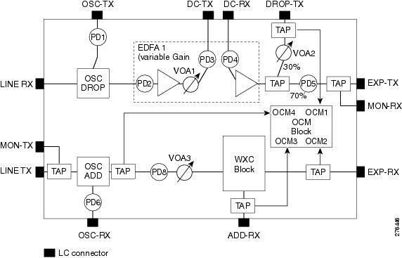
40-SMR1-C Block Diagram
Here’s a trace:
- The “LINE-RX” is where the light coming in from the previous site enters the card. For now, ignore the “LINE-TX”, but yes – that’s where light going to that site exits.
- The wavelength for the “Optical Services Channel” is split off and spit out the “OSC-TX”, which is connected to the TNCE control card.
- The rest of the light goes through Dispersion Compensation. In our case, since the light didn’t have far to go, the DC connector is simply a light loop back, with the DC-TX looped right back into the DC-RX.
- Then the rest of the light goes through a splitter; at 30% power, it’s sent out the DROP-TX (one half of the ADD/DROP connector), which is connected to the COM-RX on the corresponding shelf. That light is split, with the appropriate wavelength going into the DWDM optic’s RX port on the OTU2-XP card.
- The other 70% goes out the Express-TX port, which is connected to the other ROADM card’s EXP-RX port (and visa-versa). Keep in mind that any light not otherwise dropped off will have, on the other ROADM card, the appropriate light added, as well as the OSC-RX light added, and then that light sent out to the next site around the ring via the LINE-TX on that other ROADM.
- After the DWDM does what it does, it sends the light on through the appropriate optic (TX) which (either directly or through Y-Cable protection) connects to an RX port on the switch.
- Going back the other way, the TX port on the switch connects to the RX port of an optic on the OTU2-XP card. The DWDM-TX is connected to the appropriate channel’s RX port to be combined (if necessary) with other light.
- The COM-TX is where all that combined light comes out and goes into the ADD-RX (which is the other half of the ADD/DROP connector) on the ROADM.
- Meanwhile, the TNCE control card’s TX connector sends a signal to be added to the light signal to the OSC-RX port. This signal is added to the light coming from the EXP-RX (TX’d from the other ROADM) and ADD-RX and then sent out the LINE-TX to the other site.
Cards in our case were numbered from the bottom; Site 1’s Card 2 LINE port was connected to Site 2’s Card 7 LINE port; and then Site 2-2 to Site 1-7.
The TNCE cards actually run some software controlled through a web browser called Cisco Transport Controller, and via the OSC channel (providing stable, error-free connectivity) you can control multiple sites from a given site (also, in a given chassis, one TNCE card is active, the other standby … so you connect to the active one). It’s all GUI driven, and while CTP will export an XML file you can import into CTC, there’s still some configuration involved in setting up the circuits and protection. And then there’s debugging …
Which is why I wrote this little article. It can be very important to realize where light is actively generated or amplified and when it’s simply passed through. While the various cards have a large number of taps to let you know what the light power is at a given point, it can be helpful to know how it’s all connected together, because where you detect a problem is rarely where the problem originates. In addition, at certain points along the path, a certain amount of signal loss is to be expected, so you can avoid some confusion by being aware of that.
Mind you, in the ISP world, things get a lot more complex than our relatively simple ring around the bay will be. The chassis get larger, and the number of connections being handled are much larger than what we’re dealing with. And even if you don’t have to deal with this kind of stuff, maybe you’ll have a little more sympathy when you have to talk to the people that do.
What network engineers do often seems simple to those further up the OSI model, and the work often invisible.
We occasionally need to remember the same can be said for those who provide us services.
- Twitter: Just start your Twitter message with @BotFodder and I'll respond to it when I see it.
- Reply to the post: Register (if you haven't already) on the site, submit your question as a comment to the blog post, and I'll reply as a comment.